|
First, you have to install the following software packages
• RMCLab Client
• ALTERA MAX+Plus II or Quartus
Additionally you have to download the project template which should be the top of hierarchy graphic file (prj_01.gdf).
• Basic Information
Open MAX+Plus II (or Quartus ) and load the project template.
As you can observe there exist already several input ports (signals) that you may wish to use in your design:
- En . This signal ( En=Enable ) is asserted each time your hardware is accessed by RMCLab. We suggest you use this signal along with CLK ( i.e. En And CLK ) in order to ensure that your circuit isn't clocked when not in use.
- CLK : This is the clock signal of your project. You can adjust the frequency using the function generator of the RMCLab platform.
- AUX1 : 8 general purpose input bits connected with thumbnails that can be controlled using the RMCLab platform.
- AUX2 : 8 general purpose input bits connected with thumbnails that can be controlled using the RMCLab platform.
- MODE : 8 general purpose input bits. Note that they are not available ( do not use these lines in your design ) for this project.
Additionally, you can find 16 output lines that you can connect to the desired test points of your circuit.
It is required to combine the desired test points with the EN signal
(myTPx AND EN)
It is important to ground the unconnected test points.
• A Simple Design Example
Let's create our first simple project.
Our first project is to design a single frequency divider by 2.
The following steps illustrate how to do that:
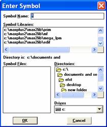
. Double click anywhere on the MaxPlusII screen. The following dialog should appear:
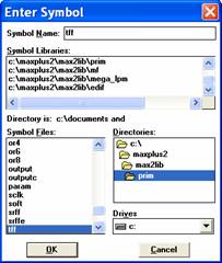
. On the Symbol Libraries list select the prim library (default installation path: c:\maxplus2\max2lib\prim)
. The Symbol Files list will be filled with all built in primitives . Select the TFF primitive and click OK
. Repeat the last step and add to your design a VCC and two AND2 primitive gates.
. Wire the several primitives to implement the circuit shown below:
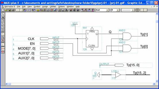
It is of high importance to notice that:
- The two test points have to be combined with the EN signal.
- All the unused test points should be grounded.
- You must not remove the unused input ports
At this point the design is finished. So you have to compile it, in order to check it for errors. Choose File->Project->Save & Compile. You may get warnings after the compilation, but you have to make sure that there are no errors .
You can download this example ( prj-02.gdf )
Now you are ready to submit your device to the RMCLab server .
• Submitting the Design to the RMCLab Server
In order to submit your design to the RMCLab server, follow the steps below:
- Run the RMCLab project client
- Provide your identification data and log in to the RMCLab server.
- Choose Upload->Project
- Press the OK button of the information form ( Note that the text is written in Greek, so, do not try to read it; it's gonna seem all Greek to you ! )
- Select the top of hierarchy file (i.e. the prj-0.gdf, or in general the name you chose when you saved your design)
- Press the Upload button to send the net-list to the RMCLab server
- Once your circuit is placed, routed and downloaded to the FPGA on the server side (this will take approx. 20-30 seconds) you will see the following window:
Now you are ready to test your circuit.
• Evaluating Your Circuit
In order to evaluate your circuit operation you have to take oscillographs from the test points you have assigned. Therefore it is mandatory to set the crucial test points when you design your circuit.
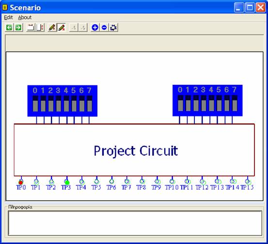
You may set the oscilloscope probes to a specific test point using the adequate buttons:

Please take into account that it is preferred to set oscilloscope's probe B to the test point which will trigger the oscilloscope's sweep.
Additionally, you can control the functionality of the circuit by setting the switches to the proper level (this depends on your design). Note that the left 8-bit switch corresponds to the AUX1-bus in the top of hierarchy schematic and consequently the right 8-bit switch corresponds to the AUX2-bus. Moreover, 0 nibble corresponds to 0-bit of the bus.
By clicking on a nibble you toggle the corresponding bit. In the previous figure the bits are defined as AUXx [ 0..7]=[10100000]
After you have set the desired test points you may adjust the frequency and the amplitude of the input clock. This can be done by applying the proper settings to the function generator.
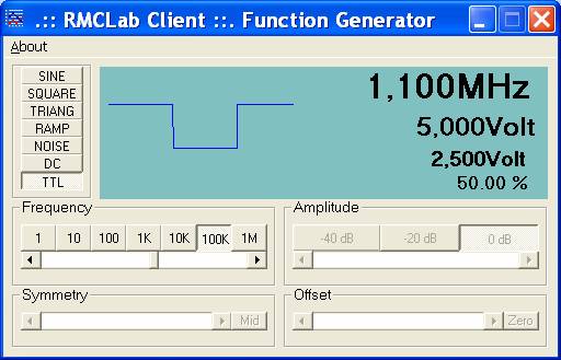
Since your project is digital, set the amplitude attenuator at 0 dB , select the TTL waveform button and adjust the frequency .
To take oscillographs use the oscilloscope.
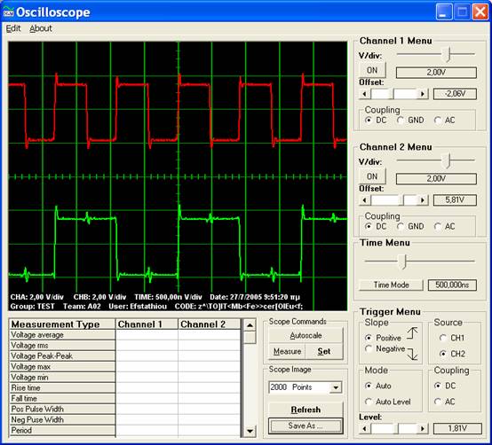
This oscilloscope operates just like a real-world oscilloscope (actually, this oscilloscope GUI controls an Agilent oscilloscope). We recommend you use the oscilloscope Autoscale feature (Scope Commands Tag) and then you get the measurements by pressing the Refresh (initially named Get Image ) button.
Enjoy RMCLab !.
|